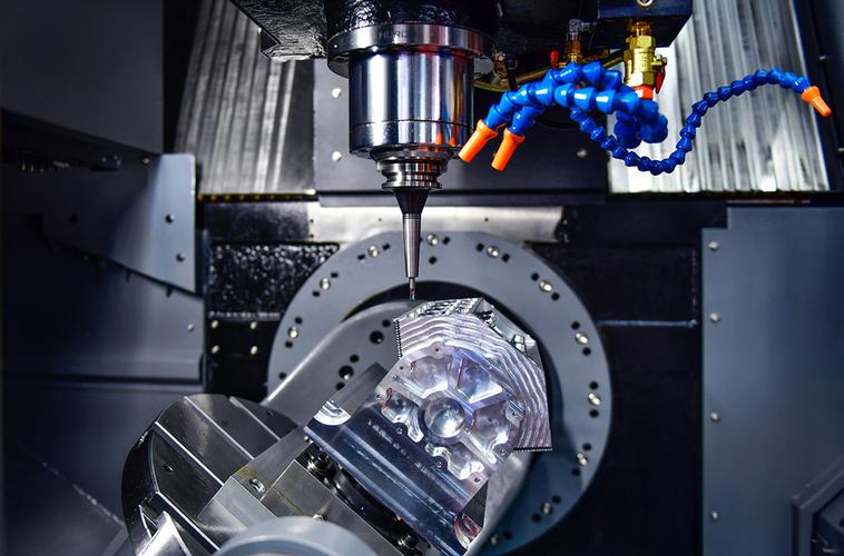
Rotary parts with composite features have always been a core challenge in process planning In the field of precision machining. They require not only guaranteed rotational accuracy for outer diameters, inner bores, and tapered surfaces, but also machining of profiled features such as flats, keyways, radial holes, and cross oil passages. The traditional split process of “CNC lathe + vertical machining center” requires multiple fixturing and alignment steps and cross-process workflow, which not only introduces unavoidable cumulative fixturing errors but also extends lead times and drives up tooling and labor costs. Turn-mill composite machining solves these pain points for this category of parts by completing all processes in a single setup.
This article systematically breaks down the core advantages of turn-mill composite machining, clarifies which kind of part suit or not suit for turn-mill composite machining, and provides actionable DFM optimization tips. Hope it helps engineers, procurement teams, and other relevant personnel quickly determine the optimal machining solution for their parts.
Blog of Outline
1. What Is Turn-Mill Composite Machining?
Turn-mill composite machining is a hybrid manufacturing technology that integrates multiple processes such as turning, milling, drilling, tapping, boring, grooving, and hobbing on a single machine, completing all or most of a part’s operations in one setup.
2. 6 Core Advantages of Turn-Mill Composite Machining
The core value of turn-mill composite machining is achieving comprehensive optimization of accuracy, efficiency, and cost for rotary parts with composite features.
2.1 Eliminates Cumulative Fixturing Errors for Significantly Improved Geometric Accuracy
Turn-Mill machining in a single setup consistently ensures geometric tolerances such as concentricity, circular runout, perpendicularity, and position, fully conforming to ASME Y14.5 and ISO 286 accuracy standards. It can control concentricity within 0.005mm, and C-axis angular positioning accuracy can reach ±0.01°.
2.2 Reduces Process Workflow for Shorter Lead Times
It eliminates waiting time for inter-process transfer, secondary fixturing and alignment, and first-article inspection across multiple operations, while reducing WIP inventory and turnover costs. For low-volume prototype parts, full-process lead times can typically be shortened by 30%–50%.
2.3 Cuts Tooling Investment & Lowers Overall Manufacturing Costs
There’s no need to design & build dedicated fixtures for separate turning and milling processes, only one fixturing scheme is required. This is especially suitable for high-mix, low-volume custom parts, greatly reducing tooling development costs and production setup time. It also cuts manual loading/unloading and process changeover labor hours, reducing labor dependency and error risk.
2.4 Excellent Batch Consistency and Stable Repeatability
All features are completed under the same machining program and same machining datum, resulting in lower dispersion of dimensional and geometric tolerances in mass production and stronger quality stability.
2.5 Reduces Post-Processing Workload for Better Surface Quality
Continuous process completion creates more stable cutting conditions, effectively reducing workpiece bruising from multiple fixturings and edge burrs from process switching. This lowers the workload and labor costs of subsequent deburring, polishing, and other post-processing steps.
2.6 Supports Complex Integrated Structures and Expands Design Flexibility
It can integrate complex features such as face milling, splines, eccentric cavities, face cams, angled oil passages, and multiple sets of cross holes on a single rotary base. This supports integrated lightweight part design, reduces assembly steps, and improves overall product reliability.
3. Which Part Structures Are Suitable for Turn-Mill Composite Machining?
Parts with a rotary body as the main structure, combined with non-rotary machining features, and clear positional accuracy requirements between features and rotary surfaces. These parts can’t be fully machined on a pure lathe and aren’t cost effective on a machining center, so turn-mill composite machining is the most cost effective solution.
3.1 Best for those Parts
Base bodies: All parts with rotary surfaces as the main structure, such as shafts, sleeves, bushings, studs, discs, and stepped rotary parts.
Additional profiled features:
Milled flats, square/hex flats, platform surfaces
Keyways, straight grooves, helical grooves, splines, retaining grooves
Radial holes, cross holes, angled holes, deep holes
Threaded holes, counterbores, counterspots, bored holes
Eccentric cavities, face grooves, cam profiles
OD/face marking/scribing, knurling
3.2 Typical Industry Applications
Hydraulics & pneumatics: Spools, valve sleeves, hydraulic fittings, valve blocks, cylinder rods
Automotive: Fuel injectors, valve assemblies, drive shafts, sensor housings
Medical: Implant grade bone screws, surgical instrument shafts, micro medical components
Aerospace: Turbine shafts, fuel fittings, landing gear pins, precision bushings
Automation: Actuation pins, motor shafts, connector pins, precision fasteners
3.3 Best Optimal Application
Feed method: Automatic bar stock feeding delivers the highest efficiency and is the ideal scenario for turn-mill composite machining.
Part size: Small to medium precision parts offer the best cost-performance ratio. Conventional machining diameter ranges from φ10 to φ200mm, and length from 10 to 500 mm.
Batch size: Highly suitable for prototype samples, low volume, and medium volume production.
4. Which Parts Aren’t Recommended for Priority Turn-Mill Composite Machining?
- Prismatic/block-based parts
- Oversized, heavy-duty workpieces
- Parts with heavy stock removal milling
- Pure rotary parts with no additional features
- Ultra high precision large flat parts
5. DFM Design Optimization for Turn-Mill Machined Parts
Targeted optimization during the design phase, combined with the process characteristics of turn-mill composite machining, can significantly reduce machining costs and improve yield and efficiency while maintaining product performance.
Design Principle | Design Requirement | Key Quantifiable Metrics | Design Self-Check Points |
Unified Datum | Key geometric tolerance datums aligned with spindle rotational center; critical features completed in single fixturing. | 100% single-fixturing completion rate; 1 datum; 0 datum conversions | Are all datums aligned with rotational center? Are there critical faces requiring secondary fixturing? |
Clustering of Similar Features | Angled holes clustered by angle; milling features clustered by region. | Minimize indexing, tool change & rapid traverse moves | Can same group angled holes be indexed in one operation? Are features interrupted by unrelated structures? |
Structural Rigidity & L/D Ratio | Steady rest for slender shafts; control width to depth ratio for deep narrow grooves; add transition fillets at corners. | L/D ≤ 10:1; groove width ≥ 1/3 groove depth; internal corner R ≥ 0.3 mm and ≥ tool radius | Are L/D & groove width ratio calculated? Are corners specified and do not interfere with mating surfaces? |
Tool Clearance Space | Reserve clearance for tool, turret, chuck, and workpiece profile; confirm tool accessibility for deep cavities. | Verify against maximum tool overhang and turret rotational envelope; mark hole/groove depth and entrance chamfer for deep holes/grooves | Does turret interfere at each indexing position? Is clearance reserved for features near chuck? Is there tool relief at deep cavity entrance? |
Dynamic Balance of Asymmetric Structures | Heavy eccentric parts require counterweighting or speed reduction. | Compare eccentric mass × speed² against allowable residual unbalance of spindle; add symmetric process bosses or counterweight holes if needed | What’s the maximum eccentric mass and radius of gyration? Does high-speed operation require speed reduction? Does counterweight position interfere with fixturing? |
Rational Tolerance Allocation | Apply high precision only to mating, sealing, and guiding surfaces; use general tolerances for cosmetic surfaces. | General tolerances standards; do not duplicate equivalent dimensional and geometric tolerances on the same feature | Is there functional justification for high precision tolerances? Are cosmetic surfaces mislabeled IT6/IT7? |
6. Core Comparison: Turn-Mill Composite vs. Split Turning + Milling
Comparison Dimension | Turn-Mill Composite Machining | Split Turning + Milling |
Fixturing Count | 1 time (dual-spindle models enable full process in single setup) | At least 2 times, more for complex structures |
Geometric Accuracy | No cumulative fixturing error; concentricity within 0.01mm | Positioning deviation exists; concentricity typically 0.02–0.05mm |
Lead Time | Short; no cross-process workflow or secondary alignment time | Long, includes transportation, multi-process inspection, and waiting time |
Tooling Cost | Low; only 1 fixturing scheme needed | High, multiple fixtures required for different processes |
Batch Consistency | Excellent; low process variation with single machine and program | Fair, prone to dispersion across multiple machines and operators |
Optimal Scenario | Small to medium batch precision parts with rotary base + composite features | Single-process features, very high volume, heavy stock removal cutting |
7. Conclusion
The advantage of turn-mill composite machining is solving the accuracy and efficiency pain points of composite rotary parts through process concentration. For parts with a rotary main body + profiled auxiliary features and positional accuracy requirements, it is currently the most cost-effective overall machining solution.
There are two core considerations to decide whether to choose turn-mill composite machining: first, whether the part main body is a rotary body; second, whether the accuracy loss and lead time cost from multiple fixturings have become core bottlenecks for the product.
If you have custom turn mill machining or metal cnc machined parts needs, welcome to provide drawings and GD&T specifications to us, we will evaluate the optimal process and provide an accurate quote.
8. FAQs
1. What level of geometric accuracy can turn-mill composite machining achieve?
With proper processes on conventional equipment, it can consistently achieve concentricity of 0.005–0.01mm, circular runout ≤ 0.008mm, position ≤ 0.01mm, and C-axis indexing positioning accuracy of ±0.01°. This fully meets precision-grade tolerance requirements under ASME Y14.5 and ISO 286 standards. Final accuracy is affected by factors such as part size, material, and length-to-diameter ratio.
2. Can turn-mill composite machining achieve 4-axis/5-axis simultaneous machining?
High end 5-axis turn-mill composite centers with a B-axis swiveling spindle can achieve 5-axis simultaneous machining of complex surfaces and angled features.RPD have basic and high-end 5-axis turn-mill composite centers, contact our team today for kick off your project.
3. Is turn-mill composite machining more or less expensive than “standard lathe + machining center”?
It depends on part structure and batch size, for small to medium batch parts with composite features, turn-mill composite machining eliminates costs for multiple tooling sets, multi-process workflow, and secondary inspection. Overall manufacturing costs are typically 15%–30% lower, and lead times are shortened by more than 30%. For very high-volume pure rotary parts with no additional features, standard CNC lathes have lower hourly costs and better cost-performance.
4. What’s the minimum order quantity for turn-mill composite machining? Can prototypes be made?
It supports the full lifecycle from single piece prototypes and low volume trial production to high volume mass production.
5. What’s the typical lead time for turn-mill composite machining?
For conventional structure parts with in-stock bar stock, prototypes can be delivered in 3–5 days, and medium-volume batches 100–500 pieces in 7–15 days. Lead times extend accordingly for complex structures or special materials requiring custom blanks.
6. Which materials are suitable for turn-mill composite machining?
Aluminum alloy, brass, free-machining steels , 304/316 stainless steel, 45 steel, alloy steel, copper alloys, Titanium alloy, nickel-based alloys (e.g., Inconel), high-temperature alloys, etc.
7. What are the size and weight limits for parts in turn-mill composite machining?
The conventional machining range for mainstream bar fed turn-mill centers: bar stock diameter φ5–φ80mm, maximum machining swing diameter φ200mm, machining length 10–500mm, and singl part weight generally not exceeding 15kg.
8. Can all features on a part be completed in one setup on a turn-mill machine?
The vast majority of rotary + composite features can be completed in one setup, but there are a few boundary limitations: deep holes/grooves beyond machine stroke or tool reach, and features requiring dedicated hobbing or grinding processes require subsequent operations.
9. What’s the difference between turn-mill composite and Swiss-type lathes? How to choose?
The core difference lies in applicable part length-to-diameter ratio and feature complexity:
- Swiss-type lathes: Specialize in slender shaft parts (L/D > 10), with extremely high pure turning efficiency. Models with live tooling can handle simple composite features, suitable for small diameter, long length simple shaft batch production.
- Turn-mill composite: Suitable for disc parts, short shafts, and sleeve parts, can integrate more complex milling, cavity, and multi-directional hole features. It has stronger process compatibility and is suitable for parts with many composite features and strict geometric tolerance requirements.
10. When to prioritize turn-mill composite, and when to choose a machining center?
- Prioritize turn-mill composite: Part main body is rotary, rotary features account for ≥60%, with a small amount of milling, drilling, and tapping features, and high concentricity and position requirements.
- Prioritize machining center: Part main body is prismatic structures such as blocks and plates, low proportion of rotary features, dominated by milling and cavity machining, with heavy stock removal requirements.
Share this article