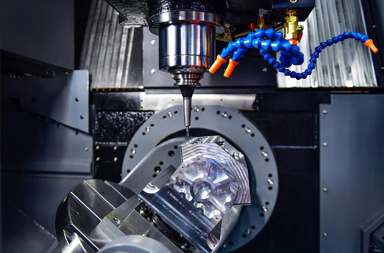
7075-T6 delivers the highest strength among commercially available aluminum alloys, with a tensile strength of 572 MPa and yield strength of 503 MPa,roughly twice the strength of 6061-T6,what makes it difficult to machine and easy to distortion.This guide list the real pain points in 7075-T6 machining and actionable methods.
Blog of Outline
1. 7075-T6 vs. 6061-T6
Property | 6061-T6 | 7075-T6 |
Tensile Strength | 310 MPa (45 ksi) | 572 MPa (83 ksi) |
Yield Strength | 276 MPa (40 ksi) | 503 MPa (73 ksi) |
Elongation (50 mm gauge) | 12% | 11% |
Brinell Hardness | 95 HB | 150 HB |
Thermal Conductivity | 167 W/(m·K) | 130 W/(m·K) |
Density | 2.70 g/cm³ | 2.81 g/cm³ |
Relative Machinability | 100 (baseline) | ~70 |
Weldability | Good | Poor; generally not recommended |
Corrosion Resistance | Good | Fair; coating or anodizing required |
2. Four key Challenges of 7075-T6 CNC Machining
2.1 Cutting Forces, Heat Generation, and Tool Life
2.2 Chatter and Tool Deflection in Thin Ribs & Thin Floors
2.3 Hole Machining and Tapping
2.4 Distortion After Unclamping and Anodizing
3. Where Does Distortion Actually Come From?
- Residual stress from the raw stock
- Machining-induced stress
- Thermal stress
- Clamping stress
4. Practical Distortion Control Methods
Control Category | Core Principle | Material Condition | Application | Key Risk |
Grade + temper | Specify temper, not grade alone | High flatness → 7075-T651; short transverse load → 7075-T7351 | Precision flat parts; structural parts under short transverse stress | Wrong temper → warpage and stress corrosion cracking |
Material standard | State the governing standard in procurement docs | ASTM B209, AMS 2770 | All aluminum plate and bar purchases | Without a standard, temper and heat treatment are untraceable |
Stock form & stress direction | Match stock form to load path | Forged stock = uniform stress; extruded profile = directional stress | Large and thick plates; load bearing structures | Never stack thin sheets to fake thick plate — warpage and delamination |
Symmetrical removal | Cut both sides equally; rough both faces before finishing | Balanced removal per side | All plate and thin wall parts | One sided heavy removal → stress imbalance, bending |
Roughing stock | Leave enough stock to absorb stress relief movement | 0.8–1.5 mm/side; large or thin parts 1.5–2.0 mm/side | Standard parts; large plates; thin walls | Insufficient stock leaves relief distortion uncorrectable |
Semi-finishing stock | Homogenize stock to stabilise finishing loads | 0.5–0.8 mm/side | Parts requiring IT7 or better | Skipping semi finishing → variable cutting force, unstable size |
Finishing stock | Light final cut to limit force and tool deflection | 0.10–0.20 mm/side | Final dimension and geometry control | Excessive depth → springback and work hardening |
Machining sequence | Datum faces first, then features referencing them | Datum first; all features locate off the datum | Multi operation complex parts | Reversed sequence accumulates datum error |
Unified datum | Set datums and fixture bosses once, reuse across operations | Datums and bosses fixed at roughing | Complex parts with multiple setups | Datum changes → per-operation checks pass, assembly fails |
Re-indication before finishing | Re-indicate before finishing to cancel roughing deviation | Dial indicator check before finishing passes | Parts with separate rough and finish operations | Unverified datums carry roughing deviation into the finished part |
Final pass parameters | Minimal depth, machined near room temperature | 0.05–0.10 mm depth; control cutting zone and machine thermal state | High precision flat and mating faces | Hot final cut drifts after cooling |
Tool selection | Fine grain carbide, sharp edges, wiper inserts | Fine grain substrate + wiper edge; 40–45° helix, 15–20° rake for thin walls | Aluminum finishing; thin wall parts | Dull tools extrude the workpiece, raising force and distortion |
Cutting strategy & toolpath | Climb mill for finishing; trochoidal for deep cavities; no full width slotting | Roughing radial 30–40% of tool diameter; finishing 10–15% | Pockets, deep cavities, thin vertical ribs | Full width slotting → force spikes, chatter, overcut |
Distributed clamping | Many light, uniform clamps instead of single point clamping | Soft jaws, even light clamping force, controlled torque | Plate and frame parts | Concentrated clamping locks distortion into the dimension |
Thin plate workholding | Zoned vacuum chuck with adjustable supports | Independent suction zones + supports | Thin, large area plates | Full surface suction without under support → springback after machining |
Ultra thin wall / thin rib | Fill the cavity to add rigidity | Wax or low melting alloy fill for walls under 1 mm | Ultra thin walls, thin ribs, deformable cavities | Milling unfilled → wall thickness tolerance unachievable |
Clamp plates & secondary setup | Clamp rigid features only; re-indicate and light clamp on second setup | Clamp points clear of thin walls; re-indicate before light clamping | Secondary setup finishing | Clamping distortion shows up directly as wall thickness error |
Cooling & lubrication | Fluid aimed at the cutting zone for heat transfer and lubrication | 8–10% emulsion; through tool coolant beyond 2× diameter | Standard milling; deep cavities | Poor cooling → thermal distortion, faster tool wear |
Precision thin wall cooling | MQL or high pressure air for precision walls | MQL / HP air instead of flood coolant | Precision thin walls and micro features | Dry roughing is not acceptable where flatness is required |
Post machining cleaning | Clean and dry immediately; no residual fluid on the part | Immediate wash + blow dry | Aluminum parts cut with water soluble coolant | Residual fluid leaches copper → white spots and corrosion |
When to stress relieve | Mandatory between roughing and finishing | Removal over 50%, or wall under 2.5 mm | High removal and thin wall components | Skipping it → continuous drift after finishing |
Relief method – natural aging | Low cost, long lead time | 24–72 h natural rest | Low volume, non urgent parts | Short rest leaves stress partly unreleased |
Relief method – low temperature | Heat treatment to shorten lead time | AMS 2770 plus written heat treat vendor parameters | Tight deadline small and medium batches | Temperature must stay below artificial aging temperature |
Relief flow for high precision | Multiple relief steps for gradual release | Roughing → relief → semi finishing → second relief → finishing | High precision, high flatness parts | Sequence cannot be compressed without losing accuracy |
Relief temperature limit | Hard limits on temperature and timing | Below artificial aging temperature; AMS 2770 + vendor parameters | All relief operations | No relief after finishing, dimensional drift |
5. Recommended Process Route for machined Thin-Wall Housings
Example: Machining a 300×200×80 mm housing with 2.0 mm wall thickness, 3.0 mm base thickness, 0.05 mm flatness, and 0.025 mm position tolerance from 320×220×90 mm 7075-T651 plate stock.
Nine-Step Process for 7075-T6 Thin-Wall Housings
Step | Operation | Stock Allowance | Key Control Points |
1 | Incoming inspection of 7075-T651 plate; record rolling direction | — | Reject plate with warpage over 1 mm |
2 | Rough mill all six faces, symmetrical removal | 2.0 mm | Move to relief once no more than 40% is removed per side |
3 | Inter operation stress relief | — | Per heat treat spec; controlled cooling |
4 | Semi finish all faces; establish datums A/B/C | 0.8 mm | All datum faces in one setup; no resetting later |
5 | Trochoidal rough pocketing, stock left on thin walls | 1.5 mm on side walls | Radial depth 25–35% of tool diameter; no full width slotting |
6 | Finish outer profile and datum faces | 0.2 mm | Clamp rigid corner sections only |
7 | Layer pocket walls and floor, 0.5 mm per layer | 0.10 mm | Radial depth 10–15% of tool diameter; fresh tool on final pass |
8 | Unclamp, re-fixture with light clamping, check relaxation | — | Re-measure wall thickness and flatness after 2 h |
9 | Final inspection | — | Equalize at 20 ± 2 °C for 24 h; CMM report to ASME Y14.5 datums |
6. Tolerance Acceptance Criteria: Depends on Inspection State, Temperature & Timing
Measuring a part on a CMM immediately after machining captures dimensions under machining heat and clamping stress, usually reading smaller or tighter. After 24 hours of rest, stress redistributes and values shift.
The acceptance state must be clearly defined on the drawing or in the contract. Measurements taken in free state, clamped state, or on an inspection fixture can differ by 0.03–0.10 mm. Without clear definition, there’s no shared standard for pass/fail, and may cause disputes between supplier and client.
Recommended Acceptance Setup
Item | Recommended Setting | Reason |
Rest time | 24 hours of free rest after machining | Allows short-term relaxation to complete and stress redistribution to settle |
Ambient temperature | 20 ± 2 °C, part fully temperature-equalized | A 5.6 °C temperature difference changes a 300 mm length by roughly 0.04 mm |
Clamping state | Free state | Clamped measurements reflect fixture dimensions, not the part itself |
Measurement method | Low-force contact or non-contact; report flatness per drawing datums | Contact force can bend thin walls |
Recheck | Take two consecutive measurements to confirm values stabilize | Unstable readings mean stress is still releasing and results are unreliable |
Report | CMM position report + datum definition + surface treatment state | Pass before anodizing doesn’t equal final part acceptance |
Achievable tolerance levels depend on part geometry. For rigid plates and blocks, ±0.01 mm position tolerance and 0.02 mm/100 mm flatness are consistently achievable. For thin-wall and deep-cavity parts, tolerance depends on the wall-height ratio; ±0.03 – ±0.05 mm is typically the practical range. Pushing tighter drives exponential increases in cost and scrap rate. Critical hole positions should be verified with CMM position reports, not calipers or plug gauges. If the part will be anodized, tolerance must account for coating thickness.
7. Common 7075-T6 Machining Issues & Controls:
Issue | Primary Root Cause | Control Method |
Post finishing flatness error / plate doming | Stock residual stress + heavy one sided cut | Use T651 plate; stress relief post roughing; symmetric removal |
Thin wall deflection, oversize, chatter | Low rigidity; radial cutting force push | Trochoidal milling; tool overhang ≤ 3×D; vacuum chuck / potting |
Surface tearing, BUE, aluminum built up on tool | Poor thermal conductivity; dull edges | High helix polished tools, ZrN / DLC coat; MQL or air blast |
Hole position drift, poor roundness | Drill extrusion + localized heat | Spot drill → drill → ream; lower feed; enhance cooling |
Tap breakage | Sticky alloy; poor chip evacuation | Form / spiral tap; tap drill +0.05 mm; EP lubrication |
Warpage after unclamping, dished base | Point clamping; cutting under load | Distributed soft jaw / vacuum clamping; clamp rigid zones only |
Anodizing: white spots, color shift, dimension change | Coolant residue, copper leaching, coating build up | Immediate clean & dry; chlorine free coolant; allowance for coating |
FA passes, fails after storage | Ongoing stress release; premature inspection | 24 h free rest before measurement; confirm stable readings |
8. DFM Tips for Drawings
Rule | Design Threshold | Consequence | Design Action |
Wall thickness | Minimum 1.5 mm for cavities up to 50 mm deep | Thinner walls require added supports, slower processing, and higher cost | No extra action needed; for walls under 1.5 mm, mark support schemes on the drawing and budget for price premium |
Base thickness | Minimum 2.0 mm base for 50 mm wide cavities | Even with perfect toolpaths, the part will dish after unclamping | Set minimum base thickness proportional to cavity width; wider cavities need thicker bases |
Corner radius | Inside corner radius ≥ 1/3 of cavity depth | Full-edge cutting at corners causes chatter, overcut, and tool deflection | Calculate minimum corner radius from cavity depth; avoid sharp deep corners |
Depth-to-diameter ratio | Cavity depth ≤ 4× tool diameter | Tolerance is limited by tool overhang and deflection, not drawing notation | Control cavity depth relative to available tool diameter; exceed only with stepped tools or multiple operations |
Tolerance type | Specify flatness for thin walls, not just thickness | A part with perfectly uniform 2.000 mm wall thickness can still be bent | Call out flatness / profile tolerance for thin-wall parts; treat thickness as reference |
Material notation | Specify temper and stress relief requirements, e.g. “7075-T651, stress relief per AMS 2770”; state whether dimensions are pre- or post-anodizing | Missing temper causes post-machining warpage and stress corrosion; mixed pre/post-anodizing dimensions cause assembly fit issues | List grade + temper + stress relief standard + dimensional reference state in drawing technical requirements |
Acceptance state | Specify free state, clamped state, or fixture state | Measured values from the three states aren’t interchangeable; high risk of acceptance disputes | Define one fixed state on the drawing or inspection spec, with clear measurement conditions |
Process bosses & sacrificial material | Allow space for temporary ribs, potting material, and fixturing features added for rigidity | No room for process aids forces slow, multi-setup workarounds for thin-wall parts | Define boss/rib locations, removal operations, and allowable residual material on the drawing |
9. Cost & Lead Time between 7075-T6 vs. 6061-T6
For equivalent sizes, 7075 plate costs 1.3–1.5× more per unit than 6061. In low-volume production, the combination of higher material removal, stress relief cycle time, and higher scrap risk pushes finished part cost to 2–3× that of 6061. For stable high-volume production, the premium typically drops to 15–30%.
Custom 7075 CNC machining parts also have 3 hidden costs:
- Tool consumption runs 30–40% higher
- Stress relief adds 1–3 days to lead time
- Inspection time nearly doubles
What more import than price is their ability to control cutting sequence, stress relief flow, and temperature conditions. A good CNC machined parts manufacturer can bring scrap rate down from 8–15% to under 2% will have lower long-term total cost, even with a higher unit price.
10. When 7075 Isn’t the Right Choice
If weight isn’t a hard constraint, wall thickness can be increased, and exceptional fatigue performance isn’t required, 6061-T6 is the more cost-effective choice.
Best application for 7075: Weight reduction is critical, parts see cyclic loading, or a hard wear-resistant surface is needed. Examples include machined fixture gages, mold inserts, robot end effectors, drone structural components, and high-pressure valve bodies.
Scenarios to avoid:
- Parts requiring welding
- Long-term saltwater / marine service without robust coating
- Large-area ultra-thin plates
Nine Steps Checklist for Design & Procurement
No. | Alignment Item | Specific Requirement |
1 | Material temper | Specify 7075-T651, not generic “7075-T6”; confirm whether need rolling direction and mill test reports |
2 | Acceptance state | Free state, clamped state or fixture state |
3 | Stress relief requirements | Whether stress relief is mandatory after roughing, and the maximum allowable heating temperature |
4 | Process bosses & sacrificial material | Drawing must allow space for temporary ribs and potting media used for rigidity |
5 | Minimum wall thickness & depth-to-width ratio | Wall thicknesses below 1.5 mm carry cost and risk that should be acknowledged on the drawing |
6 | Unified datums | All position tolerances reference the same datum set to avoid accumulated error from setup changes |
7 | Surface treatment & tolerance linkage | Whether anodizing film thickness and coating thickness are accounted for in the dimension chain |
8 | First article documentation | Release for production only with full CMM report, material MTR, and stress relief process records |
9 | Batch monitoring | Sample flatness and critical hole positions across the first 30 parts to check for batch-to-batch drift |
11. Conclusion
When specific strength is the design target, 7075-T6 is a viable choice capable of holding tight precision tolerances. Its core machining challenge lies in the coupling of high strength, low thermal conductivity, and residual stress.By selecting low-stress stock, using symmetrical cutting strategies, pairing sharp tools with distributed clamping, and defining inspection per standardized acceptance rules, most distortion risks can be anticipated at the design stage, avoiding costly scrap after the fact.
If you wanna custom 7075-T6 machined parts or metal CNC machining services, send your drawings and functional requirements to our engineering team. We’ll return DFM feedback within 24 hours, quote based on a clearly defined process route, and ship first articles with full dimensional reports measured under controlled temperature conditions.Contact our engineering team for custom 7075-T6 machined parts now.
12. FAQs
Q1: Is 7075-T6 mot easy to machine?
Yes, it’s the most demanding among common aluminum alloys. With rigid work holding, fine-grain carbide tools, climb milling, and proper surface speeds, it’s perfectly machinable.
Q2: Why does my 7075 part warp after machining?
Because internal stress is released unevenly. Stock stress, edge friction, cutting heat, and clamping force all store energy in the part.
Q3: Should acceptance inspection be done in free state or clamped state?
Free state is the default, and it must be written into the drawing or contract. Clamped and fixtured measurements reflect the fixture’s dimensions, not the part’s, and can differ from free-state measurements by 0.03–0.10 mm.
Q4: How to choose between 7075-T6 & 6061-T6?
Choose 7075-T6 when yield strength or weight drives the design. Choose 6061-T6 when rigidity is the priority, complex welding is needed, or the part will serve long-term in marine or highly corrosive environments.
Q5: Does anodizing cause 7075 to distort?
Yes. Type II builds 12–18 µm per side; Type III hard anodizing 25–50 µm. About half grows outward. Single side anodizing may bow thin plates. Specify on drawings if dimensions are measured before or after anodizing.
Q6: What’s the minimum wall thickness for 7075-T6?
1.0 mm is achievable with process stock supports, shallow cavities, and light cutting. For cavities up to 50 mm deep, 1.5 mm is a reliable production value.
Q7: Why are 7075 quotes higher than 6061?
7075 material costs 1.3–1.5× more, tools wear faster, there’s an extra stress relief step, and inspection takes longer. In low volumes, the finished cost per good part can be 2–3× an equivalent 6061 part. Once the process is dialed in, the premium is usually only 15–30%.
Q8: What temperature is used for inter-operation stress relief?
It must remain below the artificial aging temperature. Follow AMS 2770 and written parameters from your heat treat vendor.
Share this article