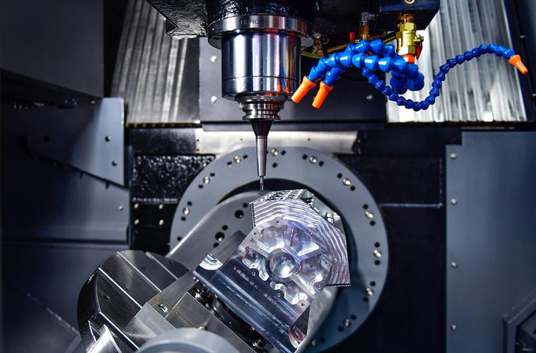
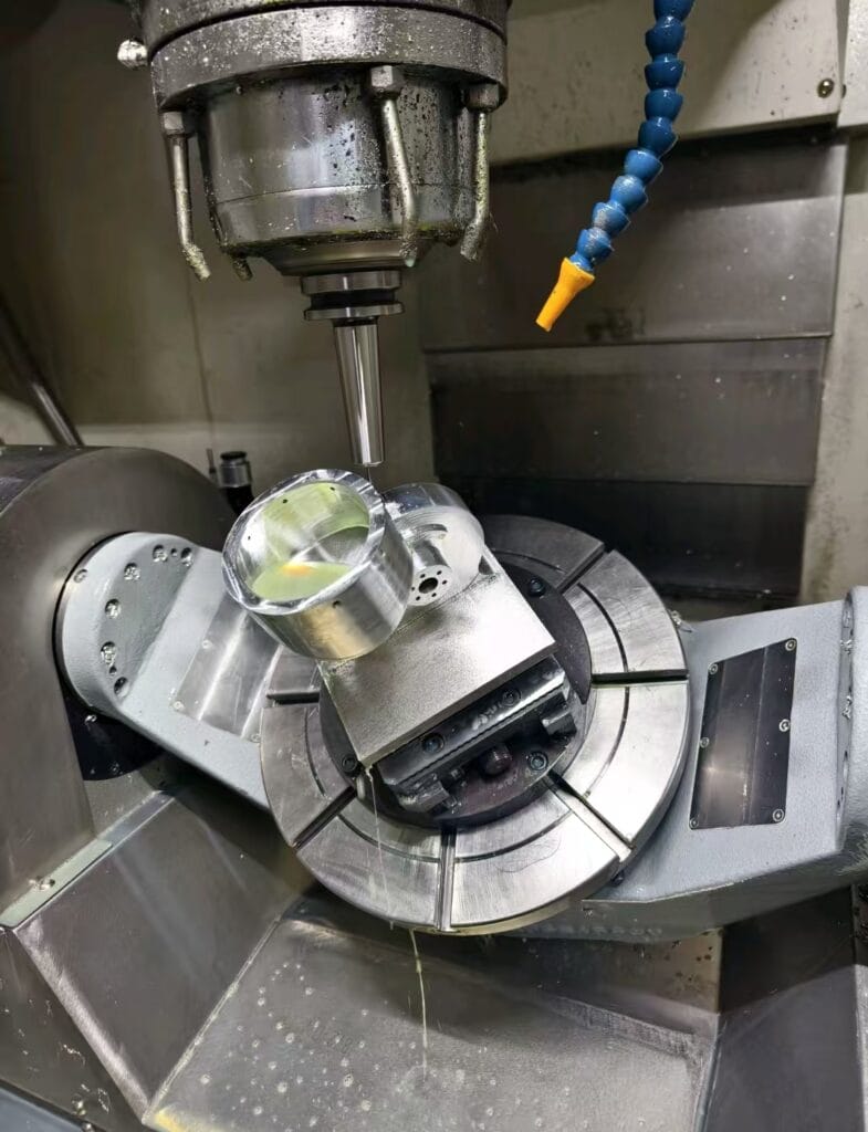
Let’s cut straight to the point: this article focuses on stably achievable IT tolerance grades and Ra surface roughness ranges for 3-axis and 5-axis milled parts in volume production. It also sorts out typical DFM design pitfalls and optimization suggestions, delivering actionable precision references for part design, specification selection and procurement.
Blog of Outline
1. Three Precision Tolerance Standards for CNC Machining
There are 3 complete precision specification standards for mechanical parts: linear dimensional precision, geometric form and position precision, and micro surface precision.
- ISO 286 IT Grade: Officially the Geometrical Product Specifications (GPS) linear dimensional tolerance standard. It defines 20 accuracy grades from IT01, IT0 through IT18. Higher numbers mean wider tolerance bands and lower precision. This globally accepted baseline controls deviation ranges for linear dimensions (length, diameter, thickness, answering “is the size correct?”).
- ASME Y14.5 GD&T: The geometric dimension and tolerance(GD&T) standard widely used in North America. It governs form, position and orientation of geometric features such as flatness, concentricity and position tolerance, answering “are the shape and location correct?”.
- ISO 4287 / ASME B46.1 (Ra): Controls micro scale undulations on part surfaces, answering “is the surface smooth enough?”.
1.1 Dimensional Tolerance System: ISO 286 as Foundation, ISO 2768 for Volume Production Simplification
Industry practice applies the ISO 2768-1 general tolerances for dimensions without individual tolerance indications. it’s a simplified execution rule derived from ISO 286 IT grades. It consolidates scattered IT grades into four general precision classes to govern all linear dimensions that carry no explicit tolerance notes on drawings.
Correspondence between ISO 2768-1 classes and ISO 286 IT grades for reference:
- Fine (f): roughly IT7~IT8
- Medium (m): roughly IT9~IT10
- Coarse (c): roughly IT11~IT12
- Very coarse (v): roughly IT13~IT14
Important note: IT grades only define tolerance band width. Actual design needs tolerance band positions (deviation letter codes) alongside IT grades to fully define fit requirements. For milled features, use the hole basis system H for holes and shaft basis system h for shafts. Common mating surface combinations include H7/h6 and H8/h7. For non-mating dimensions, use JS/js (symmetrical deviations).
1.2 Geometric Tolerance System: ASME Y14.5 Position & Boundary Rules
- IT grades apply solely to linear dimensional tolerances.
- No direct conversion exists between IT grades and ASME Y14.5 GD&T values.
1.3 Surface Roughness: The Third Standard Beyond Dimension and Geometry
Dimensional tolerances plus geometric tolerances alone can’t fully define machining requirements. That’s why we introduce the Ra arithmetic mean roughness parameter.
Per ISO 4287 / ASME B46.1 definitions, Ra is the arithmetic average of absolute value height deviations between the actual micro surface profile and its midline over the evaluation length. It’s the most widely used surface finish metric on engineering drawings and for CNC machining.
A complete production drawing normally specifies three groups of precision requirements: tolerances / IT grades on critical dimensions, GD&T controls for geometric features, and Ra roughness values for functional surfaces. Together they determine final part performance and assembly compatibility.
2. Achievable Precision for 3-Axis CNC Milling
2.1 Economic & Limit Ranges for IT Tolerances
For volume 3-axis CNC milling: the economic tolerance range for functional mating surfaces is IT9~IT10. Non-assembly structural surfaces can relax to IT11.
- IT8 counts as precision milling. It calls for dedicated finishing end mills, stable machine tools and a temperature controlled shop environment. Simple small size parts within 100 mm can hit IT8 consistently in volume, yet yield drops sharply for large size or complex geometry components.
- IT7 and finer precision can’t be reliably achieved with standard milling for mass production. Secondary processes such as grinding or honing are usually required, and costs rise exponentially.
- IT12 and looser tolerances fall under rough machining specs, only for non mating structural shaping without assembly needs.
2.2 Volume Production Reference Values for Geometric Tolerances
Below are economic volume production reference values for 3-axis finish milling under standard fixturing for features within 100 mm.
Geometric Tolerance Type | Economic Achievable Value | Precision Controlled Limit Value |
Flatness | 0.02~0.05 mm | 0.01~0.02 mm |
Parallelism / Perpendicularity | 0.03~0.08 mm | 0.02~0.03 mm |
Positional tolerance for hole patterns | ±0.05 mm | ±0.03 mm |
Concentricity | 0.04~0.08 mm | 0.02~0.04 mm |
Note: When part dimensions exceed 200 mm, multiply geometric tolerance values will be higher. For thin wall or deep slot low rigidity structures, relax tolerances by one additional grade.
3. Tighter tolerances NOT means better surface roughness.
The two correlate but don’t have mandatory fixed relationships. Standard milling has economic matching ranges for IT tolerance grades and roughness.
4. CNC Milling Tolerance & Roughness for Different Materials
Material Group | Common Grades (ASTM / DIN) | Economic Tolerance | Best Volume Production Tolerance | Typical Ra (μm / μin) | Notes |
Aluminum Alloy | 6061-T6 ASTM B221 / DIN EN AW 6061 | IT9 | IT8 | 0.8 / 32 | Excellent machinability and low tool wear. High thermal expansion coefficient. Thin wall or large size parts easily deform. Apply stress relief aging for high precision requirements. |
Carbon Steel | 1018 ASTM A108 / DIN C15 | IT9 | IT8 | 1.6 / 63 | Stable cutting behavior and low fixturing related deformation. Base material is relatively soft. Grinding is usually needed for premium surface quality. Uncoated surfaces rust easily. |
Stainless Steel | 304 ASTM A276 / DIN 1.4301 | IT10 | IT9 | 3.2 / 126 | High ductility promotes built up edge formation. High cutting heat accelerates tool wear. To hit Ra<1.6 μm you’ll need high speed milling or multiple finishing passes, which raises costs. |
Copper Alloy | C11000, C36000 ASTM B152 / DIN CW614N | IT9 | IT8 | 0.8 / 32 | Free cutting brass machines very well. Pure copper is soft and gummy, easy to generates heavy burrs. |
Titanium Alloy | Ti6Al4V Grade 5 ASTM B348 / DIN 3.7165 | IT10 | IT9 | 1.6 / 63 | Low thermal conductivity traps cutting heat at cutting edges. Use low feed rates and dedicated tooling. Material costs are high. Aggressive cutting parameters burn workpiece surfaces. |
Engineering Plastic | POM ASTM D6100 / DIN EN ISO 1043-1 | IT11 | IT10 | 1.6 / 63 | Easy to machine with good surface finish. Low heat distortion temperature. Cutting heat causes dimensional drift. Not suited for tight tolerance mating features. |
Specialty Alloys | 17-4PH / Invar 36 ASTM A564 / ASTM F1684 | 17-4PH: IT11; Invar: IT10 | 17-4PH: IT10; Invar: IT9 | 1.6 / 63 | 17-4PH: strong work hardening, heavy abrasive tool wear and high tool loads. Invar 36: ultra low thermal expansion for metrology grade parts; |
Carbon Fiber Reinforced Polymer (CFRP) | CFRP (T700 / T800) | IT11 | IT10 | 3.2 / 126 | Highly abrasive to cutting tools. Main failure risks are delamination and fiber pull out. Use sharp diamond coated cutters. Edge sealing is critically important. |
Glass Fiber Reinforced Laminate | G10 / FR4 ASTM D709 / DIN EN 60893 | IT11 | IT10 | 3.2 / 126 | Extreme tool abrasion. Brittle substrate tends to chip at cut edges. Not suitable for high precision continuous surfaces. |
5. IT Tolerance and Ra Roughness Comparison for 3-Axis CNC Milling
Roughness represent typical post finish mill results with no secondary surface treatment.
Size Range mm / in | IT7 mm / in | IT8 mm / in | IT9 mm / in | IT10 / IT11 mm / in | Economic Ra Range & Process μm / μin |
0–10 / 0–0.39 | 0.015 / 0.0006 | 0.022 / 0.0009 | 0.036 / 0.0014 | IT10: 0.058 / 0.0023IT11: 0.090 / 0.0035 | 0.4–12.5 / 16–500 Roughing through high speed finishing |
10–30 / 0.39–1.18 | 0.021 / 0.0008 | 0.033 / 0.0013 | 0.052 / 0.0021 | IT10: 0.084 / 0.0033IT11: 0.130 / 0.0051 | 0.8–12.5 / 32–500 Roughing through finish milling |
30–100 / 1.18–3.94 | 0.035 / 0.0014 | 0.054 / 0.0021 | 0.087 / 0.0034 | IT10: 0.140 / 0.0055IT11: 0.220 / 0.0087 | 0.8–12.5 / 32–500 Roughing through finish milling |
100–200 / 3.94–7.87 | 0.046 / 0.0018 | 0.072 / 0.0028 | 0.115 / 0.0045 | IT10: 0.185 / 0.0073IT11: 0.290 / 0.0114 | 1.6–12.5 / 63–500 Roughing through semi finishing |
200–500 / 7.87–19.69 | 0.063 / 0.0025 | 0.097 / 0.0038 | 0.155 / 0.0061 | IT10: 0.250 / 0.0098IT11: 0.400 / 0.0157 | 1.6–12.5 / 63–500 Roughing through semi finishing |
500–1000 / 19.69–39.37 | 0.080 / 0.0031 | 0.125 / 0.0049 | 0.200 / 0.0079 | IT10: 0.315 / 0.0124IT11: 0.500 / 0.0197 | 1.6–12.5 / 63–500 Roughing through semi finishing |
1000–2000 / 39.37–78.74 | 0.105 / 0.0041 | 0.165 / 0.0065 | 0.260 / 0.0102 | IT10: 0.420 / 0.0165IT11: 0.660 / 0.0260 | 3.2–12.5 / 126–500 Roughing through semi finishing |
Remarks:
- IT7 is not an economically viable volume production tolerance grade. Only use it for small size critical mating features. Large size parts hitting IT7 almost always require grinding.
- IT8 and finer tolerances demand 20 °C temperature controlled environments plus metrology tools such as micrometers or CMMs. Measurements taken in uncontrolled shops need to compensate for dimensional shifts caused by material thermal expansion.
- For dimensions larger than 500 mm, relax volume production economic precision by one grade compared with the under 100 mm range. Don’t force IT8 or tighter requirements.
6. 5-Axis Milling Tolerance & Roughness
- 3+2 Axis: Its precision matches comparable 3-axis machines. Volume production economic tolerances land at IT9~IT10. Simple small size features under 100 mm can reach IT8 with finish milling.
- Full 5-Axis Simultaneous Machining: Spindle, rotary tables tilt and rotate in real time for free form surfaces, undercuts, impellers, mold cavities and similar geometries. Backlash in rotary axes, following error and tool center point compensation degrade linear dimensional performance. Tight end to end process controls can limit degradation to about half an IT grade. Volume production economic tolerances are IT10~IT11. Rigorous process control can get close to IT9. Typical economic profile tolerance for simultaneous 5-axis finish milling runs 0.05-0.1 mm (0.002-0.004 inch).
6.2 Ra Roughness Performance for 5-Axis Milling
- For planes and inclined surfaces machined in 3+2 axis mode: roughness results match 3-axis milling. 6061 aluminum can hit Ra 0.8 μm (32 μin) after finish milling. Carbon steel and stainless steel performance follows the same patterns as 3-axis work.
- For curved surfaces from simultaneous 5-axis cutting: ball end mill step over and rotary axis feed fluctuations drive typical economic Ra to 1.6-3.2 μm (63-126 μin). High-speed milling paired with small step overs can reliably achieve Ra 0.8 μm (32 μin) on aluminum curved surfaces, yet cycle time increases by over 30% and costs jump significantly.
- For deep cavities and undercut features: when tool overhang exceeds three times tool diameter, cutting chatter pushes roughness up one to two grades while widening achievable tolerances.
6.3 Economic Precision Comparison: 3-Axis vs. 5-Axis
Machining Process | Volume Production Economic IT Grade | Precision Limit IT Grade | Typical Economic Ra Range μm / μin | Primary Application Scenarios |
Standard 3-Axis Milling | IT9~IT10 | IT8 | 1.6~6.3 / 63~250 | Simple geometry parts with planes, slots and holes completable in one fixturing setup |
3+2 Axis Milling | IT9~IT10 | IT8 | 1.6~6.3 / 63~250 | Parts with multi face features, angled planes and angled holes that would otherwise need two to three 3-axis re-clamps |
Simultaneous 5-Axis Milling | IT10~IT11 | IT9 | 1.6~3.2 / 63~126 | Complex geometries: free form surfaces, undercuts, impellers, mold cavities |
6.4 Key 5-Axis Precision Trade-Offs and Common Pitfalls
- Precision degrades sharply with growing part size. Controlling geometric tolerances becomes far harder than on 3-axis machines. Don’t insist on IT8 or tighter grades.
- Cost versus performance boundaries: machine hour costs for 5-axis work run 2-3 times higher than equivalent 3-axis jobs. 5-axis delivers net value only when 3-axis would demand three or more re-fixturing steps or must tackle non-machinable undercuts or curved surfaces.
- Most frequent failure modes: specifying IT grades for curved surfaces, or forcing IT8 across every feature on a part. Simultaneous 5-axis can’t consistently hold IT8 linear tolerances on curved geometry.
7. Surface Treatment Ra Change Reference Table
Surface treatments directly modify surface roughness. Most also alter dimensional tolerances. Designers must leave proper machining allowances early in the design phase to stop out of spec dimensions or unsatisfactory roughness after finishing.
Surface Treatment Process | Main Applicable Materials (ASTM / DIN) | Required Base Material Ra Before Treatment μm / μin | Typical Post Treatment Ra Range μm / μin | Key Trade Offs & Notes |
Blasting (glass bead / aluminum oxide) | 6061 Aluminum (ASTM B221/DIN EN AW-6061), 1018 Carbon Steel, 304 Stainless Steel | ≤12.5 / ≤500 | 1.6~12.5 / 63~500 | Hides tool marks and scratches for uniform cosmetic appearance. Raises overall roughness and removes 0.01 0.05 mm substrate material, which impacts tight tolerance dimensions. Finer blast media delivers lower Ra at higher cost. |
Conventional Sulfuric Acid Anodizing | 6061 / 7075 Aluminum Series | ≤3.2 / ≤126 | 1.6~3.2 / 63~126 | Porous oxide film usually slightly increases Ra; final Ra never falls below original substrate Ra. At 10-20 μm film thickness, unilateral dimensional growth equals roughly half the total film thickness. |
Hard Anodizing | Aluminum Series | ≤1.6 / ≤63 | 1.6~6.3 / 63~250 | Thick, hard coating that noticeably raises roughness. With 25-50 μm film thickness, unilateral dimension shift is substantial. Relax tolerances in advance. |
Mid-Phosphorus Electroless Nickel Plating | Carbon Steel, Stainless Steel, Aluminum | ≤1.6 / ≤63 | 0.4~1.6 / 16~63 | Uniform coverage over complex geometries and mild roughness improvement. Consistent 5-20 μm unilateral plating thickness. Subtract plating allowance for tight-tolerance features. |
Electropolishing | 304 / 316 Stainless Steel (ASTM A276/DIN 1.4301 / 1.4401) | ≤1.6 / ≤63 | 0.2~0.8 / 8~32 | Significantly lowers Ra and boosts corrosion resistance. Removes 0.01-0.03 μm base material. Risks dimensional non-conformance on precision parts. Not suited for sharp edges. |
Mechanical Polishing | All Metals | ≤3.2 / ≤126 | 0.1~1.6 / 4~63 | Can achieve mirror finishes. Doesn’t polish deep cavities or complex curved surfaces evenly. Polishing removes substrate material and modifies dimensions. |
Shot Peening | Carbon Steel, Stainless Steel, Titanium Alloy | ≤12.5 / ≤500 | 3.2~12.5 / 126~500 | Optimized for improved fatigue strength; roughness goes up. Induces surface compressive stress. Thin wall parts risk distortion. Not recommended for high precision components. |
Black Oxide / Bluing | Carbon Steel Grades (ASTM A108/DIN C15) | ≤3.2 / ≤126 | 1.6~3.2 / 63~126 | Very thin coating (<2 μm). Barely changes roughness or dimensions. Only improves cosmetics and rust resistance. Preferred for tight tolerance carbon steel parts. |
Passivation | Stainless Steel Grades | ≤3.2 / ≤126 | Nearly identical to pre-treatment value | Only enhances corrosion resistance. Doesn’t alter surface topography or dimensions. Top pick for tight tolerance stainless steel components. |
8. Practical DFM Design Recommendations
- Apply tiered tolerance marking; never enforce uniform precision across the whole drawing. Assign tight tolerances only to mating surfaces, locating holes and datum faces. Relax non-mating cosmetic and structural surfaces to IT10~IT11.
- Intentionally relax tolerances for large size parts. Don’t demand IT8 or tighter for components over 200 mm (7.87 inch).
- Add tolerance allowances for special geometry features. Thin wall sections (<2 mm / 0.079 inch), deep slots (depth to width ratio >3:1) and cantilever structures suffer tool deflection and fixturing driven deformation. Relax tolerances by at minimum one IT grade.
- Match roughness and tolerances; avoid over specification. Ra 3.2 μm (126 μin) fully satisfies cosmetic requirements for surfaces with no assembly function. Assign roughness values for sealing faces and mating surfaces consistent with their tolerance grades.
- Define datums and tolerance types following ASME Y14.5. Don’t just add a drawing note reading “machine to IT7”. Write explicit upper and lower limit deviations for linear dimensions. Separate geometric tolerance annotations must include clear datum references. Different manufacturers interpret IT grades differently. Hard coded numerical values cut miscommunication and volume production variation.
9. Conclusions:
If you have request of metal CNC machining services, send your RFQ with drawings & functional requirements to our engineering team. We’ll return DFM feedback within 24 hours.Contact our engineering team for custom CNC machined parts now.
10. FAQ
Q1: What are the economic tolerance grades for regular CNC milling?
For 3-axis CNC volume production, IT9-IT10 represent the cost optimal band for functional mating surfaces. Non-mating structural surfaces can relax to IT11. This window maximizes machining speed, yield stability and cost efficiency. Prototyping samples can reach IT8. IT7 and finer need special process controls and carry steep cost increases.
Q2: Do I need secondary finishing to reach Ra 1.6 μm surface roughness?
Easy to machine materials such as aluminum and low carbon steel consistently hit Ra 1.6 μm (63 μin) with standard finish milling. Hard to machine grades including stainless steel and titanium often require high speed milling or multiple finishing passes. Polishing may be necessary in some scenarios.
Q3: Do drawings following ASME Y14.5 need IT grade annotations?
ASME Y14.5 doesn’t mandate IT grade call outs. Directly write limit deviations for dimensions plus associated geometric tolerances. Use IT grades during design phase grade selection. Avoid placing raw IT grade notes on released production drawings.
Q4: Why do large size parts cost more for the same IT grade?
IT grades express relative tolerance bands. As nominal size grows, absolute tolerance band values increase. Large size components compound errors from machine travel inaccuracies, material deformation and fixturing challenges. Holding the same relative precision IT grade costs significantly more for bigger workpieces.
Q5: What IT tolerance grade corresponds to Ra 1.6 μm?
No strict one to one mapping exists. Parts finished to Ra 1.6 μm with conventional milling often hold IT8-IT7 dimensional tolerances, but that’s a side effect of the process, not a guaranteed pairing. When you need both tight dimensions and defined roughness,contact our team for verification.
Q6: Are milling capability differences across materials significant?
Very significant. Aluminum offers the best machinability and can achieve tighter tolerances and smoother surfaces at given cost levels. Stainless steels and superalloys suffer from difficult cutting behavior, so holding equal IT grades costs substantially more.
Q7: How do I cut costs on tight tolerance parts?
Assign tight tolerances only to functionally critical mating surfaces and relax everything else. Optimize part geometry to boost structural rigidity. Pick easily machined materials and so on, For DFM and cut cost, do not hesitate to contact our team for more details.
Share this article