Blog Outline
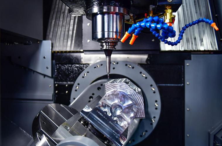
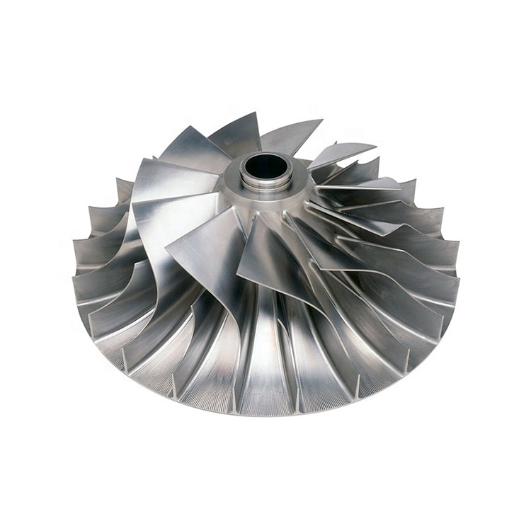
You must know over-specified chamfers, fillets, and edge breaks are invisible cost killers in CNC custom machining. They do not improve part functionality, safety or durability, but significantly increase machining difficulty, cycle time, tool wear & inspection costs.
1.What are Chamfers, Fillets and Edge Breaks in Precision Machining?
Here is practical definitions and machining characteristics in 5-axis milling, precision turning and mill-turn hybrid machining:
Chamfers:
Sloped flat edge cuts processed via single-pass standard end mills or chamfer tools. Common specifications include 45° chamfers with 0.5mm–2mm width. Chamfer machining features simple tool paths, stable cutting status, and short cycle time, making it the most cost effective edge processing solution for non stress edges.
Fillets (Radius Edges):
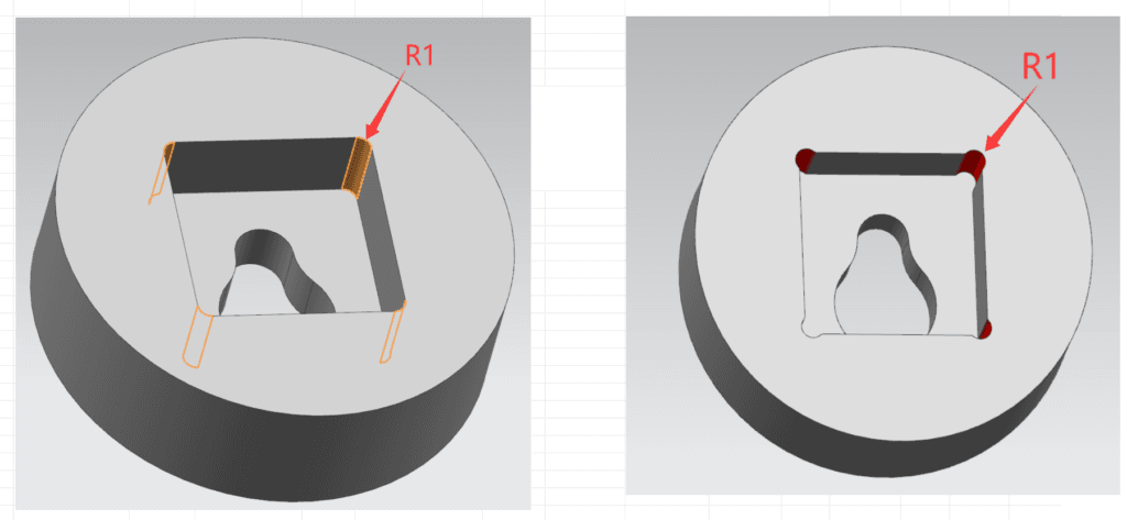
Arc transition edges requiring circular interpolation cutting. Small fillet radii (below R0.5mm) need ultra-small-diameter tools, while internal fillets cannot be processed with standard large tools. Fillet machining requires multiple cutting passes, precise tool path calibration, and strict vibration control, resulting in far higher time and tool wear costs than chamfers.
Edge Breaks:
General deburring and edge rounding processes for sharp part edges. The industry default standard is 0.5mm uniform edge break for all non-specified sharp edges, which is completed via automatic post-processing without additional quotation charges. Over-specification refers to mandatory fixed-size, tight tolerance edge breaks on all edges, including non assembly and non-contact idle edges.
Common applicable materials for edge feature processing cover 6061/6063/7075 aluminum, 303/304/316 stainless steel, POM, PEEK, and titanium alloy, covering all mainstream precision custom parts for industrial and high-end applications.
2. Why Over Specified Edge Features Increase CNC Machining Costs?
Every over-specified chamfer, fillet, and edge break on drawings translates to tangible extra costs in actual production. Combined with our full inspection process and ±0.001mm – ±0.005mm high precision machining standards, excessive edge requirements amplify production difficulty.
2.1 Extra tool switching and longer cycle time
Standard CNC batch production follows fixed tool sequences to ensure efficiency and stability. When designers specify diverse chamfer sizes, tiny fillets, and full-edge edge breaks, machinists have to frequently switch between standard milling tools, chamfer-specific tools, and small-radius profiling tools. Each tool switch involves tool setting calibration, coordinate correction, and trial cutting, consuming 5–20 minutes of auxiliary time per batch.
For complex automation and machinery custom parts with dozens of edges, repeated tool switching can increase total machining cycle time by 20%–40%.
2.2 Small Non Standard Radii Require Low Rigidity Tooling
Designing such tiny non standard inner chamfers like R0.2 mm and R0.3 mm is an expensive design. Standard cutting tools can’t handle these small radii, so specialized slender, low stiffness small diameter tools must be used.
These thin and delicate tools are prone to deflection and vibration when processing hard materials such as stainless steel or titanium alloys. We have to reduce the feed rate and add extra cutting processes. Sometimes we even need to perform a secondary electrical discharge machining to meet the design requirements.
2.3 Add Extra labor
In our plant, standard sharp edge debur is a free auxiliary process for all CNC parts. However, full edge mandatory edge breaks with fixed tolerance requirements, requiring manual finishing and extra dimensional inspection.
For batch custom automotive and automation parts, full edge manual edge break inspection increases labor costs by 15%–25%.
2.4 Increased tool wear, scrap rate & secondary processing risks
Continuous small radius fillet cutting & frequent chamfer processing accelerate tool wear, especially for PEEK, titanium alloy, and stainless steel parts. Worn tools produce unqualified surface finishes and dimensional errors, raising the product scrap rate. Our factory data shows that parts with over-specified edge features have a 12%-15% higher rework rate than standard designed parts.
3. Extra Cost Details:
Features | Extra Cost reasons |
Chamfers (Bevels):non-standard angles, multi-sided bevels, and very small sizes require separate tool setting. | Change of tool + Number of tool movements |
Fillets (rounded corners): Excessively small R values significantly increase the processing time. | Small-diameter cutting tools + Multiple-edge deburring |
Edge Breaks: When not marked, we will default to rounding the sharp edges. If each edge is marked on the drawing as “0.2×45°”, it will become a mandatory inspection item. | Manual deburring + Inspection |
4. How to avoid?
Just follow below rules:
4.1 Follow DFM Optimization Rules of Cost Effective Chamfer & Fillet Specifications
Based on nearly 20 years of precision machining experience & DFM design standards, Shenzhen RPD Industrial team knew practical edge specification rules to eliminate redundant costs while ensuring part safety and functionality.
4.2 Follow industry standard default edge break tolerance
Accept tool‑radius residue and adopt the universal industry standard: 0.5mm default edge break for all sharp edges without special instructions. This standard meets assembly safety and anti-burr requirements, and can be completed by automatic processing with zero extra cost.
4.3 Choose chamfers over fillets for non stress critical edges
Under the same functional requirements, chamfer processing cost is 40%–60% lower than fillets. Chamfers adopt single pass cutting with stable efficiency and low tool wear, making them the best choice for ordinary edge transition. Fillets are only reserved for positions requiring stress dispersion and smooth transition.
4.4 Avoid full part uniform over specification
Do not apply unified tight-tolerance edge requirements to the entire part. Classify edge levels according to usage scenarios.
Reserve strict tolerance chamfers and fillets only for functional edges.
5. Machining Case Studies
We processed 1000pcs of 6061 aluminum automation custom parts for a US regular client last month. The original design specified uniform R0.25mm tiny fillets and 0.9mm fixed chamfers on all edges, which required 6 tool switches per part, 22 minutes for a single-piece cycle time.
Our DFM optimization suggestions: retain precise fillets only for stress bearing assembly edges, and adopt standard 0.6mm edge breaks for other idle edges. Our client accept the optimization, the tool switching times were reduced to 2 times, single-piece cycle time was shortened to 15 minutes. Of course, the benefit is the quote price was reduced by 31%, and the lead time was shortened by 34%, zero impact on part assembly and service performance.
6. Summaries
Reasonable edge feature specification is one of the most efficient ways to reduce custom part costs. Here is Quick Cost Saving Checklist:
1. Cancel uniform tight tolerance edge requirements for non-functional edges
2. Replace unnecessary tiny fillets with standard chamfers
3. Adopt industry default 0.5mm edge break for general deburring
4. Avoid non standard special sized edge features that require customized tools
5. Classify edge tolerance standards according to functional importance
We support ±0.005mm high-precision machining, full dimension inspection, one-stop OEM/ODM solutions, and fast lead time to help you reduce production costs and ensuring part quality. Contact us now!