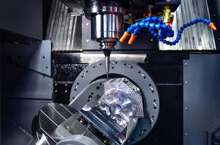

Beyond metal materials, engineering plastics are also widely applied in CNC machining. Due to the inherent properties of it, various issues often arise during custom manufacturing of plastic parts. For example, drawings specify a precision tolerance of ±0.01 mm (±0.0004 inch), but actual machining results may show ±0.03 mm(±0.0012 inch). The root cause lies not in machine tool accuracy, but in mismatched material grades, poor cutting heat management, inappropriate work holding solutions and misalignment with ASME tolerance standards.
This article covers the most mainstream general-purpose engineering plastics used in CNC machining. It compares grade performance, typical machining defects, machining process trade-offs, tolerance setting, surface roughness selection and cost control across six dimensions, helping you balance precision, yield and unit cost while avoiding repeated sampling and rework.
Blog Outline
1. CNC Machining Comparison of Engineering Plastics
PMMA (Acrylic) vs POM (Delrin) vs PA66(Nylon 66) vs PC vs ABS vs PET vs PPS vs PSU vs PEI vs PEEK
The machining stability, coefficient of thermal expansion and moisture absorption rate of engineering plastics directly determine whether parts can maintain dimensional tolerance stably.
Material Grade | Material Category | Core Advantages | Typical Limitations | Raw material Cost |
POM (Delrin) | Semi-crystalline engineering plastic | Excellent dimensional stability, low moisture absorption, low friction, low tendency to stick to cutting tools | Relatively high brittleness, prone to chipping at sharp corners | $$ |
PA66 (Nylon 66) | Semi-crystalline engineering plastic | High strength, self-lubricating and wear-resistant | High hygroscopicity; dimensional drift caused by temperature and humidity changes; prone to softening when overheated during cutting | $$ |
PC (Polycarbonate) | Amorphous transparent plastic | Outstanding impact resistance, semi-transparent | Poor thermal conductivity; highly prone to heat accumulation and cracking; significant elastic yielding in thin-walled parts | $$ |
PMMA (Acrylic) | Amorphous optical plastic | Light transmittance ≈92%, good weather resistance, excellent optical grade after flame polishing | High brittleness, sensitive to cutting heat; turns cloudy/opaque when overheated; chipping under improper clamping | $$ |
ABS | Amorphous general-purpose plastic | Low raw material cost, easy to machine, suitable for rapid prototyping | Low heat deflection temperature; easily melts and sticks to tools above 80℃ | $ |
PET / PETP | Semi-crystalline engineering plastic | Low moisture absorption, creep resistance, wear resistance, better cost-performance than POM | Weak low-temperature impact performance | $ |
PPS (Polyphenylene Sulfide, GF-reinforced) | Semi-crystalline high-temperature engineering plastic | High temperature resistance, chemical resistance, self-extinguishing, extremely low water absorption | Glass fiber filler causes severe tool wear; high brittleness, prone to chipping at corners; not suitable for optical surfaces | $$$ |
PSU (Polysulfone) | Amorphous high-temperature transparent plastic | Amber transparent, hydrolysis-resistant, withstands repeated steam sterilization | Poor thermal conductivity; cutting stress easily induces delayed cracking; requires annealing after machining | $$$$ |
PEI (Ultem) | Amorphous high-temperature transparent plastic | High rigidity, extremely low creep, excellent long-term thermal stability | High cost, strict requirements for cutting edge sharpness | $$$$$ |
PEEK | Semi-crystalline high-performance plastic | High temperature resistance, hydrolysis resistance, creep resistance, top-tier dimensional stability | High raw material cost, rapid tool wear, long machining time | $$$$$$ |
Core Selection Principles: Prioritize POM for dynamic precision sliding components; choose PMMA (acrylic) for optical transparent windows; prefer PET for wear-resistant backing plates and conveying jigs; select PPS for high-temperature, corrosion-resistant and insulating parts; choose PSU for applications requiring transparency + high-temperature sterilization; select PEI for high-stability jigs in aerospace and semiconductor industries; use ABS for low-budget, non-load-bearing housings; avoid pure PA66 in humid environments.
2. Key CNC Machining Challenges of Plastics
The machining mechanism of engineering plastics is completely different from metals. Almost all problems revolve around three points: machining heat, material elastic deformation and residual stress.
First, extremely poor thermal conductivity with highly concentrated heat at the cutting edge.
Second, elastic yielding, chatter marks and brittle chipping.
Third, post-machining war page and stress cracking from blank residual stress.
Fourth, burrs and post-processing limitations.
3. Process Trade-offs & Machining Strategy
When machining plastic parts, trade-offs must be made between cutting speed, feed rate, tooling, cooling and work holding based on experience, to balance machining efficiency and dimensional accuracy.
3.1 Cutting Tool Selection
Prioritize 2-flute carbide tools with large chip flutes and mirror-polished surfaces; Transparent materials (PMMA, PC, PSU, PEI) must never be machined with dull tools edge wear will directly leave foggy surfaces and tool marks. For acrylic machining, dedicated acrylic end mills with sharper edges and larger chip evacuation grooves are recommended. Filled materials (PPS, glass-filled nylon) can use diamond-coated tools to extend service life; avoid multi-flute mills, as more flutes increase friction and heat accumulation. Use positive rake angles for POM, PET and PEEK to reduce cutting resistance; further increase rake angles for PMMA and PC to reduce chipping and melting.
3.2 Cutting Parameter Trade-offs
Adopt high spindle speed, shallow depth of cut and reasonable feed rate to enable fast chip evacuation, carry away heat and shorten tool contact time. Cooling strategy is a key trade-off: the vast majority of plastics are not suitable for liquid cutting fluids. Hygroscopic materials like nylon and PSU will absorb coolant and deform; acrylic surfaces prone to watermarks after polishing when exposed to moisture. The optimal solution is continuous high-pressure air cooling. Only a small number of PC parts and thick acrylic plates can use atomized cold air. For optical finishing of acrylic, dry air cooling is preferred, and coolant moisture should be isolated as much as possible.
3.3 Workholding and Process Sequencing
Brittle transparent parts (PMMA, PSU) must not be clamped with hard vise jaws at single points. It is recommended to pad with soft wood or rubber gaskets to distribute pressure. For large-area acrylic thin plates, full-surface vacuum chuck adsorption is preferred to avoid local cracking.
Unified process logic: rough machining → stress relieving standstill → semi-finishing → second clamp loosening and standstill → final finishing. For highly stress-sensitive materials like acrylic, PC, PSU and PEI, the stress relieving step can’t be omitted. For POM & PET, the standing time can be shortened according to tolerance grade. For thin-walled parts, clamp step by step instead of locking all at once.
4. Tolerance & Dimensional Control Recommendations
Many engineers directly apply metal part tolerance specifications, which is the primary cause of plastic part over-tolerance. All CNC machining tolerances for engineering plastics must be based on ASME B89.6.2 at a reference temperature of 20°C, combined with thermal expansion and ambient temperature considerations.
1. Standard production tolerance (no temperature-controlled workshop):
POM, PET: ±0.03~±0.05 mm (±0.0012~±0.0020 inch)
PA66, ABS: ±0.05~±0.10 mm (±0.0020~±0.0040 inch)
PMMA (acrylic), PC, PSU: ±0.05~±0.10 mm (±0.002~±0.004 inch); up to ±0.15 mm for large-size acrylic parts
Glass-filled PPS: ±0.04~±0.08 mm (±0.0016~±0.0032 inch)
2. Precision-grade tolerance (temperature-controlled workshop + complete stress relief process):
POM, PET, PEEK: consistently achieve ±0.01~±0.025 mm (±0.0004~±0.0010 inch)
PMMA, PSU: optical features can be controlled to ±0.025 mm, but only suitable for small-size rigid structures; tight tolerance isn’t recommended for large-area windows
3. Key reminders:Do not unnecessarily tighten tolerances on non-critical features, each precision grade increase leads to exponential growth in machining time and scrap rate.
5. Surface Finishing Options for Engineering Plastics
For custom plastic machining parts, different treatments correspond to fixed Ra ranges and suit different application scenarios.
- As-machined finish: Ra 0.8~3.2 μm. First choice for general structural parts and POM/PET jigs, with the lowest cost. Acrylic as-machined surfaces leave fine tool marks visible during light transmission, so they can’t be used directly as optical surfaces.
- Hand polishing:Ra 0.2~0.8 μm. Preferred for POM sliding friction surfaces. Acrylic hand polishing can eliminate tool marks but with average consistency and high labor cost.
- Vibratory deburring & finishing:Ra 1.6~6.3 μm. For high-volume ABS and PPS housings to remove filament and chip burrs. Not suitable for acrylic optical surfaces.
- Flame polishing:Exclusive process for PMMA acrylic. Can achieve Ra below 0.1 μm, eliminating tool marks and restoring high light transmission. Limitations: can’t process inner holes and small grooves; PC can also be flame polished, but is more prone to internal stress cracking use with caution.
- Chemical polishing:Only applicable to a small number of specialty plastics, with high risk and unstable precision. Only used for appearance display parts; strictly prohibited for mating dimensions with tight tolerances.
- Stress relief annealing:Not an appearance polishing process, but a critical post-process for PSU, PEI, acrylic and PC. Eliminates machining residual stress and prevents subsequent cracking and deformation. Often used for optical and medical parts.
Plastic machined parts surface finish selection tips: Prioritize flame polishing for acrylic optical windows; polish sliding friction surfaces to Ra ≤ 0.8 μm; keep as-machined finish for general jigs and backing plates (PET/POM); generally avoid high-gloss polishing for glass-filled PPS parts.
6. Cost Factors & Practical Selection Tips
The total cost of CNC machined plastic parts is determined by three components: material cost, machining time cost & scrap cost. In many cases, switching material grades can reduce total cost by more than 40%.
First, huge price gap in raw materials. PEI and PEEK have the highest unit prices; followed by PSU and PPS; PET and POM fall in the cost-effective range. PMMA has moderate raw material price, but premium for optical finishing is very high. ABS is the cheapest.
Second, machining time cost depends on processing difficulty. Brittle transparent parts like acrylic and PSU require reduced feed rates, resulting in significantly longer machining time than POM and PET. Glass-filled PPS causes rapid tool wear and frequent tool changes, which also increases cost. Thin walls, deep grooves and tight-tolerance parts directly double machining time and increase scrap risk simultaneously. Design adjustments such as larger fillets, increased minimum wall thickness and avoiding single-point clamping can significantly reduce acrylic chipping scrap rates.
Third, tighter tolerances equal higher costs. Tightening acrylic tolerance from ±0.1 mm to ±0.025 mm requires temperature-controlled workshops, multiple finishing passes and annealing, increasing machining time by at least 70%. When reviewing drawings, distinguish between functional dimensions and appearance dimensions. For acrylic windows, prioritize relaxing body tolerances and only tighten positioning holes and assembly borders.
7. Conclusion
The core logic of CNC machining engineering plastics isn’t simply pursuing machine tool accuracy, but forming a complete closed loop of material grade selection, cutting heat management, stress relief, ASME tolerance benchmarking and surface finishing.
Quick Selection Guide for Sourcing: ① Normal-temperature precision sliding fits: POM; wear-resistant backing plates & jigs: PET ② Transparent windows, light guide structures: PMMA (acrylic) ③ High-temperature, chemical-resistant, insulating & flame-retardant: glass-filled PPS ④ Transparent + high-temperature steam sterilization: PSU; high-stability high-temperature jigs: PEI ⑤ High-temperature long-term creep applications: PEEK ⑥ General housing prototypes, tight budget: ABS ⑦ Humid environments: avoid pure PA66.
Unsure about cnc machining materials? Welcome you reference our CNC materials selection page & click our other blog of CNC stainless steel guide, carbon steel grade selection, CNC machined alloy steel material selection, Aluminum CNC materials Selection.
If you have RFQ of machined plastic parts , our engineering team can provide free drawing tolerance review, optimized structural design, the most cost-effective material and process solutions. Welcome to send your drawings for an accurate CNC machining quote.
FAQ
1: What tolerance can CNC machining hold for acrylic PMMA parts?
Under standard conditions, acrylic consistently holds ±0.05~±0.10 mm (±0.002~±0.004 inch). With temperature control + annealing + precision finishing, small rigid features can achieve ±0.025 mm (±0.001 inch). Tight tolerances are not recommended for large-area windows.
2.Why does acrylic turn cloudy after CNC cutting?
Excessive cutting heat causes the acrylic surface to melt and re-solidify, forming a foggy surface. It requires sharper tools, high-pressure air cooling and reduced feed rates. Optical parts can be repaired with subsequent flame polishing.
3.What is the difference between PSU, PEI and PPS for CNC machining?
PSU is transparent and hydrolysis-resistant, suitable for steam sterilization. PEI has high rigidity and low creep, mostly used in semiconductor fixtures. PPS (filled grade) has high temperature and chemical resistance, but contains glass fiber which causes fast tool wear and isn’t suitable for optical parts.
4. Is PET plastic a good choice for CNC wear plates and jigs?
Yes. PET has low moisture absorption, good wear resistance, low tendency to stick to tools, and dimensional stability close to POM at a lower price. It is a cost-effective choice for jig backing plates and conveying rollers.
5. Can we use flood coolant for acrylic CNC machining?
Not recommended. Coolant moisture easily leaves watermarks on polished surfaces and also aggravates internal stress cracking. High-pressure cold air and dry cutting are preferred.
6. Which plastic material is best for optical windows CNC parts?
For CNC optical parts machining of transparent plastics, PMMA is the first choice, with excellent light transmittance & great optical effect after flame polishing. PC has better impact resistance, but is more prone to hidden stress cracks after polishing.
7. Do PSU and PEI parts require stress relief after CNC machining?
Yes. Both are amorphous high-temperature plastics. Machining cutting stress can easily induce post-machining cracking. Stress relief annealing must be added before precision finishing.
Share this article