For lightweight structural design, carbon fiber reinforced polymer (CFRP) is an option for engineer. It offers far higher specific strength than 6061 aluminum alloy, weighs only one-fifth as much as steel, and delivers excellent fatigue and corrosion resistance.
Based on hands-on mass production experience, this guide covers the most widely used industrial grades (T300, T700, T800 and more). For CFRP CNC machining, we outline core challenges, process trade-off logic, tolerance control limits, surface finishing solutions and cost considerations, helping you bypass common design-stage pitfalls and achieve a balanced mix of performance, manufacturability and cost.
Blog of Outline
1. Common CFRP CNC Machining Materials Comparison
CFRP performance is determined by three factors: carbon fiber tow, matrix resin, and layup structure. In industrial mass production, 90% of orders fall into the 6 grade systems below.
Material Grade | Key Mechanical & Material Properties | Machining Characteristics | Typical Applications | Selection & Process Notes |
T300 Standard Modulus (Toray baseline grade) | Tensile modulus 230GPa, tensile strength 3530MPa; most common is 3K plain/twill weave + epoxy matrix | Most machinable of all grades; fibers cut cleanly; standard carbide tools handle regular milling and drilling; well-stocked market, stable lead times | RC model structural parts, general tooling fixtures, cosmetic decorative parts, non-load-bearing lightweight enclosures | Not recommended for primary load-bearing structures, long-term operation above 150°C, or high-impact load conditions. Top choice for cost-sensitive batch orders. |
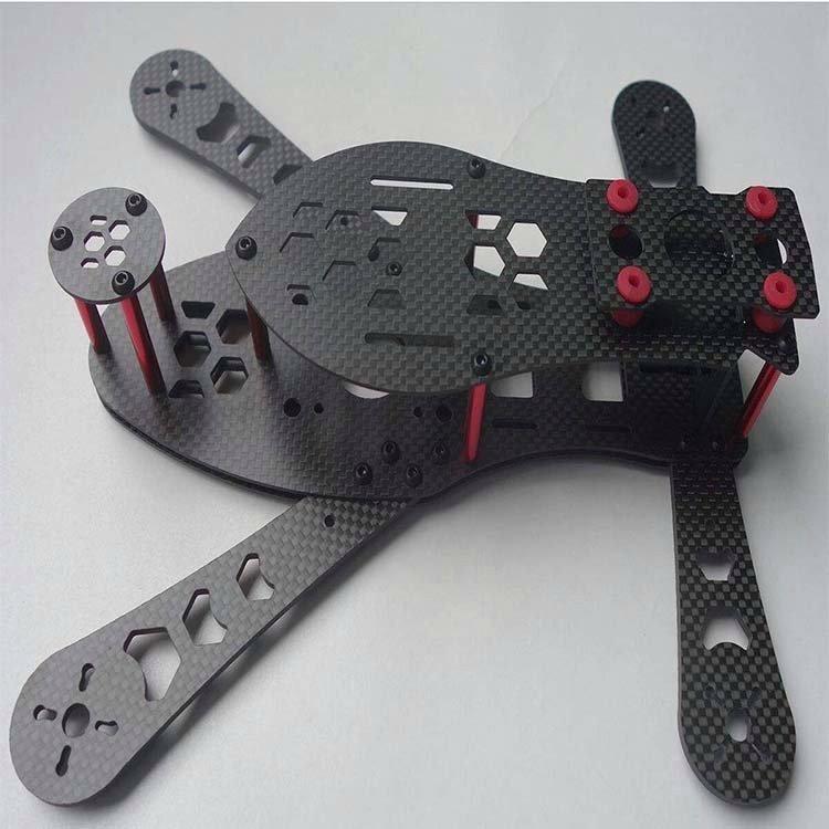
T700S / T700G High Strength Standard Modulus | Tensile modulus 230~240GPa, tensile strength 4900MPa; most common is 12K unidirectional layup / 3K twill + epoxy matrix; T700G has stronger interlaminar bonding | Slightly harder to machine than T300; transverse cutting of 12K unidirectional plate is prone to fiber pull-out; T700G has ~15% lower delamination risk than T700S | Drone load-bearing frames, industrial robot arms, automotive aftermarket structural parts, inspection tooling | Requires optimized cutting edges and feed direction; diamond coated tools are recommended for medium batches and above for better total cost. |
T800H / T800S Intermediate Modulus High Strength | Tensile modulus 294GPa, tensile strength 5500MPa, excellent CAI performance; commonly uses high-temp epoxy / BMI matrix, long-term heat resistance 180~230°C | Significantly higher machining difficulty; fiber hardness causes extremely rapid carbide tool wear; improper parameters cause inlet/outlet delamination; thin-wall parts prone to chatter and out-of-tolerance issues | Aerospace secondary structures, racing components, high-end wind energy equipment, high-load precision tooling | PCD diamond tools are preferred for mass production; cutting parameters and clamping force must be strictly controlled to avoid crushing and hidden cracks. |
T1000G / T1100G Ultra-High Strength Intermediate Modulus | T1100G tensile modulus 324GPa, tensile strength 7000MPa; high-end aerospace epoxy matrix, top-tier strength for mass-produced materials | Machining difficulty similar to T800, even higher requirements for tool sharpness; expensive raw materials, long lead times, some grades subject to export restrictions | High-end aerospace structural parts, satellite load-bearing structures | Very rarely used for general industrial projects; only recommended for aerospace custom orders with explicit high-strength requirements. |
M40J / M55J High Modulus Carbon Fiber | M55J tensile modulus up to 540GPa; near-zero coefficient of thermal expansion, excellent dimensional stability | Extremely difficult to machine; fibers are brittle, highly prone to microcracks and interlaminar delamination, high scrap rate | Optical reference parts, satellite antenna mounts, precision inspection tooling | Requires PCD diamond tools + dedicated support tooling; highly customized high-difficulty machining, high cost, long lead time. |
CF/PEEK Thermoplastic Carbon Fiber Composite | Continuous / short carbon fiber reinforced PEEK matrix; heat resistant, chemical resistant, repeatedly sterilizable, better toughness than thermoset CFRP | No fiber fuzzing, low delamination risk; resin tends to stick to tools, cutting temperature must be controlled | Medical precision parts, semiconductor tooling, chemical-resistant structural parts | Not suitable for high-speed dry cutting; requires sharp tools and temperature-controlled cooling to avoid resin melting and tool buildup. |
2. Core Challenges in CFRP CNC Machining
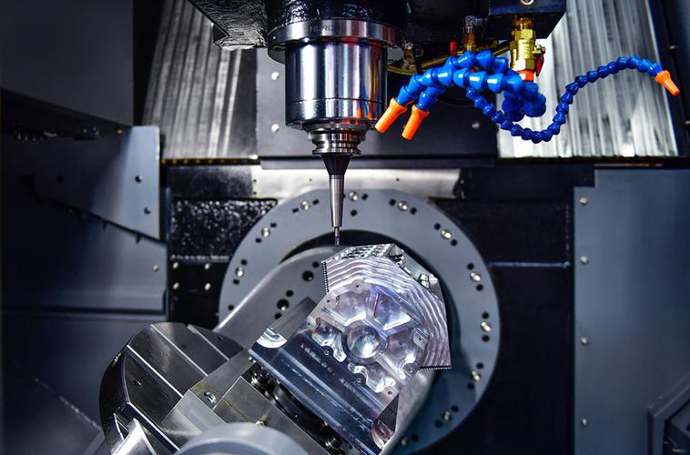
Unlike the plastic deformation mechanism of metal cutting, CFRP is a two-phase composite of fiber and resin. The cutting process is a combination of “fiber shearing + resin peeling”. There are 5 core challenges:
- Interlaminar delamination
- Fiber pull-out and fuzzing
- Thermal damage and resin degradation
- Conductive dust hazards
- Workholding and thin-wall distortion
3. Process Trade-offs & Carbon Fiber CNC Machining Strategy
No universal CFRP machining recipe. Parameters balance quality, throughput and piece cost; routes change with modulus, thickness, tolerance and finish.
Tool Selection
- Ultra-fine carbide: T300 prototyping. Poor for T700+; edge honing not recommended.
- Diamond coating: Mid-cost, mid-life for medium-batch T700.
- PCD: Best for high-volume, high-precision & T800+. Clean cuts, high upfront cost, not repairable if chipped.
Cutting Rule
High RPM, low feed, shallow cut. Sharp edges shear fibers to reduce delamination, fuzzing and resin heat damage.
Cooling
- Dry: Standard + dust extraction, for thin-plate light cuts
- Cold air: Precision work, residue-free cooling
- MQL: Longer tool life; incompatible with bonding, vacuum holding or painting
- ❌ Water coolant banned: causes hydrolysis and strength drop
Workholding
Vacuum clamping preferred. ≥5 mm plate in vise: soft jaws, light clamp force. <5 mm / perforated parts: vacuum + conformal support to stop chatter & delamination.
Process Tips Separate rough/finish, leave 0.2–0.3 mm stock per side. Holes: pre-drill + ream; large holes: helical interpolation. >10 mm plate: peck drilling for chips & heat control.
4. CFRP CNC Machining Tolerances
The anisotropic nature of CFRP means it can’t achieve the same high precision as metals. Per ASME Y14.5 standards, our tolerance recommendations are:
Tolerance Item | Economic Tolerance (Preferred for Batch Production) | Precision Tolerance (High-End Equipment / Tooling) |
Overall linear dimensions | ±0.005” (±0.127mm) | ±0.002” (±0.05mm) |
Bore diameter tolerance | ±0.003” (±0.076mm) | ±0.0015” (±0.038mm) |
Hole position tolerance | 0.008” (0.203mm) | 0.004” (0.102mm) |
Required process support | Achievable with standard CNC equipment, lowest machining cost | Requires PCD diamond tools, vacuum clamping fixturing, and temperature-controlled workshop for stable mass production. |
Compatible material grades | Stable for T300, T700 and other conventional CFRP sheets | Only recommended for T700 and above with more uniform material properties; not advised for thin-wall parts. |
Typical use cases | General industrial structural parts, cosmetic decorative parts, non-fit functional parts | High-end equipment assemblies, precision inspection tooling, high-precision fit components |
Dimensional Control Notes
- Thickness tolerance: The as-received carbon sheet thickness tolerance is typically ±0.004”/±0.1mm. Machining can’t change the base material tolerance, so don’t specify overly tight thickness requirements in design.
- Dimensional stability: CFRP absorbs moisture and swells. Epoxy matrix experiences ~0.05%–0.1% dimensional change after moisture absorption. High-precision parts require drying treatment and edge sealing, and tolerances should include allowance for this effect.
- Thin-wall and long cantilever structures: Tolerances should be appropriately relaxed, otherwise chatter will cause dimensional deviation. We recommend at least 50% relaxation.
5. Surface Finishing Options for CFRP Machined Parts
Surface Finish Option | Typical Roughness | Core Process Features | Applications | Cost & Notes |
As-machined surface | Ra 1.6–3.2μm | As-milled / turned state, clear weave texture, no extra post-processing | Internal structural parts, non-visible surfaces, general parts with no sealing or weather resistance requirements | Lowest cost; edges have tiny burrs, removed by hand deburring. |
Sanded & polished surface | Ra 0.2–0.4μm | Progressively sanded and polished with sandpaper, fine surface finish, greatly reduced fiber texture | Cosmetic parts, sealing fit faces, optical accessories | Higher labor cost than as-machined; sanding removes surface resin and exposes fibers, so edge sealing is mandatory to prevent water absorption. |
Epoxy edge sealing / clear coat | Depends on base surface (usually retains sanded / as-machined texture) | Sprayed with transparent epoxy clear coat to seal fiber cut pores, suppress water absorption and delamination, improve weather resistance | Outdoor service parts, humid environment components, cut edge protection after sanding | Adds ~5%–10% cost vs. as-machined; applied mainly to machined cut edges and sanded surfaces. |
Matte / gloss surface painting | Smooth paint surface, no visible fiber texture | Full spray of polyurethane / epoxy paint, available in black, gray and other solid colors. Fully covers carbon fiber texture, scratch and wear resistant. | Equipment enclosures, exposed cosmetic parts, structural parts requiring uniform color scheme | Moderate to high cost; coating adds 0.02–0.05mm thickness, so fit surfaces require dimensional allowance in advance. |
Conductive / shielding coating | Depends on base surface and coating process | Sprayed conductive paint or copper-nickel plating, EMI shielding effectiveness over 60dB | Communication equipment housings, electronic chassis, components requiring EMI shielding | Higher cost; coating changes surface dimensions, not suitable for long-term high-temperature service. |
6. Cost Factors & Practical Selection Advice of Carbon Fiber CNC Machining Service
CFRP machining costs vary drastically. Identical-size parts can see over 5× price gaps between T300 and T800.
Key Cost Drivers
- Material grade: For 3 mm epoxy CFRP sheets, T300 ≈ 60% of T700’s price; T700 ≈ 40% of T800’s price. High-modulus M-series fiber runs 2–3× T800 cost. CF/PEEK thermoplastic stock is far pricier than standard epoxy CFRP.
- Complexity: Cutouts, thin walls, deep grooves and micro holes increase fixturing difficulty, tool wear and cycle time. A part with 50% material removal costs 2–3× more than a solid blank of the same outline.
- Tolerance & finish: Tight precision tolerances add 30%–80% cost vs. standard tolerances. Mirror polish and custom coating also raise labor expense.
- Order volume: Low-run prototypes (1–10 pcs) carry high unit cost from programming, fixturing and tool setup amortization. For runs over 100 pcs, unit cost falls 40%–60%.
7. Precision Carbon Fiber Machining Quick Selection Guide
Material Series | Ideal Applications | Not Suitable For | Cost Tier | Machining Traits |
T300 3K twill epoxy plate | Cosmetic parts, decorative surfaces, non-load-bearing structural parts | Load-bearing structures, high-load conditions | Lowest | Machining friendly, uniform texture, low scrap rate |
T700G epoxy plate | Drones, automation equipment, load-bearing frames | Extremely high temperature / extreme loads | Medium (best cost-performance) | Moderate machining difficulty, stable mass production |
T800H BMI / high-temp epoxy plate | Aerospace, racing, high-temperature conditions | Room-temperature general applications (not cost-effective) | High | Mature process, stable supply chain |
High-modulus M series | Optics, satellites, precision structures | General industrial parts (unnecessary) | Very high | High machining difficulty, requires special processes |
CF/PEEK thermoplastic carbon fiber | Medical, semiconductor, corrosive environments | General conditions (too expensive) | High | Sterilizable, corrosion resistant (don’t substitute with epoxy carbon fiber) |
When CFRP Isn’t the Right Choice
- Frequently disassembled threaded holes: CFRP threads have low strength and strip easily. Metal inserts are preferred.
- Long-term operation above 200°C: Standard epoxy carbon fiber fails; BMI only goes up to 260°C. For high-temperature conditions, ceramics or high-temperature alloys are better choices.
- High impact load, easily bumped scenarios: CFRP is brittle. Impact causes internal delamination, and cosmetic damage is irreversible.
- Extremely cost-sensitive general parts: For equivalent strength, 6061 aluminum costs only 1/3–1/2 of CFRP.
8. Conclusion
For CFRP machined parts material selection, follow this rule: on the premise of meeting performance requirements, prioritize grades with good machinability and mature supply chains. If T300 works, don’t use T700. If epoxy matrix is sufficient, don’t use BMI. If economic tolerances meet requirements, don’t specify precision grade.
Our team has 15 years of experience in CNC machining of composite materials. We provide full-process service from material selection and process optimization to mass production. If you have custom CFRP part needs, or machining requirements for aluminum, stainless steel, carbon steel, copper, titanium, engineering plastics or special materials, contact our engineering team for free DFM analysis and an accurate quote. Welcome you reference our CNC materials selection page & click our other blog of CNC stainless steel guide, carbon steel grade selection, CNC machined alloy steel material selection, Invar low expansion alloy, Inconel CNC machining, Aluminum CNC materials Selection.
9. FAQ
1. What tools are best for machining carbon fiber composites?
For small-batch prototyping, ultra-fine grain solid carbide tools work well. For medium-batch production, diamond coated tools are recommended. For T800 and above high-modulus carbon fiber, or high-precision batch orders, PCD polycrystalline diamond tools are preferred for more stable machining quality.
2. What’s the machining difference between T300 and T700 carbon fiber?
T300 has finer fibers, uniform weave, better machinability, slower tool wear and lower cost. T700 has higher strength. 12K unidirectional T700 plate is prone to fiber fuzzing during machining, has higher requirements for tool sharpness, and higher material and machining costs than T300.
3. What causes delamination in CFRP machining? How do you prevent it?
Delamination is mainly caused by dull tools, excessive feed rate, and lack of back support at the hole exit. It can be effectively reduced by using sharp tools, controlling cutting parameters, adding back support for hole machining, and using helical interpolation for milling holes.
4. Can you tap threads directly in carbon fiber plate?
Yes, you can tap threads. Generally, threads M3 and larger can be machined directly in carbon plate. But CFRP threads have low strength and strip easily, so they’re only suitable for low-load, infrequent disassembly scenarios. For frequently disassembled threads, we recommend pre-embedded metal thread inserts or copper bushings.
5. Which is harder to machine: CFRP or G10/FR4?
CFRP is harder to machine. G10/FR4 is glass fiber epoxy with softer fibers, and doesn’t delaminate easily during machining. CFRP carbon fiber has high hardness and strong anisotropy, is prone to delamination and fuzzing, has higher requirements for tools and processes, and higher machining cost.
6. What’s the typical lead time for small-batch CFRP parts?
1–10 piece prototype lead time is usually 4–5 business days. For batch orders with complex structures, special grades or surface treatment requirements, lead time is 8–25 business days.
7. What’s the machining difference between thermoset and thermoplastic CFRP?
Thermoset CFRP (epoxy / BMI matrix) is hard and brittle, prone to delamination and fuzzing during machining, requires diamond tools. Thermoplastic CFRP (like CF/PEEK) has good toughness, no delamination or fuzzing issues, but resin tends to stick to tools, so cutting temperature must be controlled.
Share this article